1. Introduction
Hello and welcome back to the 2nd part of our blog post series summarizing our research in the fields of UEFI fuzzing and exploitation. In part 1 of the series, aptly titled “Moving from common-sense knowledge about UEFI to actually dumping UEFI firmware”, we gave some highly-condensed yet required background information on the SPI flash memory, and discussed the software-based approach to dump it to disk. We concluded that part by unpacking the firmware image using a myriad of tools.
This part picks up where we left off. We’ll start by giving some more background information on UEFI in general, both from the viewpoint of the boot process itself (what are the different boot phases? How are they related? etc.) as well as from the viewpoint of developers (i.e. what APIs are available to UEFI applications). From there we’ll move on to manually reverse engineer some UEFI modules. Throughout this post, we’ll slowly but surely make our way towards more and more dynamic approaches. If you follow along this post, by the time you finish reading it you’ll have a working environment capable of emulating, tracing and debugging UEFI modules.
Let’s get going.
2. UEFI Boot Phases
As a painful lesson learned from legacy BIOS, UEFI tries to make the boot process as methodical and organized as possible. For that reason, the UEFI specification divides the boot process into disparate phases, each in charge of setting up specific components crucial for the sound operation of the machine. After a certain phase is done, it should pass control to the next phase in the chain, possibly with some auxiliary data to help it carry out its actions. Graphically, the UEFI boot process is often depicted using hard-to-grasp diagrams, filled with little known acronyms such as SEC, PEI, DXE, BDS, etc.
Figure 1 – the UEFI boot process (source: sudonull)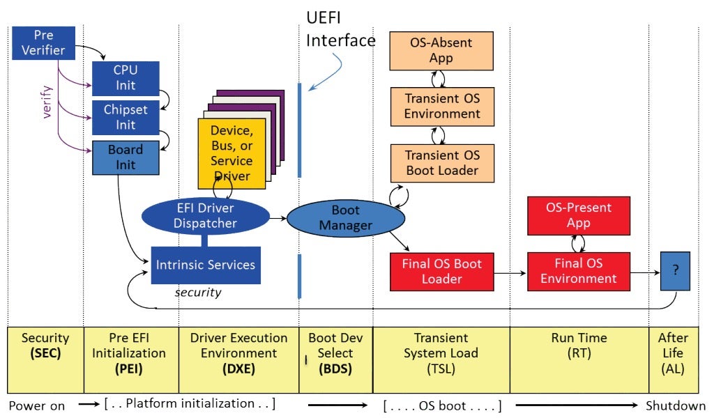
An accurate and comprehensive review of the boot process, which also includes some attack-surface analysis, was written a while ago by @depletionmode. Here we’ll just give a short overview of each of each of these phases.
- SEC phase: Contrary to the popular myth, when booting in UEFI environments the CPU doesn’t magically start executing in 32-bit Protected Mode or 64-bit Long Mode. Rather, the first few instructions executed by the CPU are still legacy, 16-bit Real Mode instructions. Since very little can be done in Real Mode, one of the first jobs of the SEC phase is to switch the processor to Protected Mode. Also, by this time the memory controller in charge of DRAM has not been initialized yet, and so the SEC phase is also in charge of configuring the CPU caches to be used as temporary RAM (a technique known as CAR – Cache-as-RAM).
- PEI phase: The Pre-EFI Initialization phase, often shortened to just PEI, usually resides in its own firmware volume (FV) on the SPI flash. It is composed of executable modules which adhere to a file format called TE (Terse Executable), closely related to the well known PE format from Windows.
The PEI phase is in charge of main memory discovery and initialization. After main RAM becomes available, the PEI phase can wind up CAR memory and move on to initialize a bunch of other devices on the motherboard. To pass information down to the DXE phase, PEI modules can create and populate an array of data structures called HOBs (Hand-Off Blocks).
- DXE phase: The Driver Execution Environment, or DXE phase for short, is where most of the heavy lifting takes place. Like the PEI phase, the DXE phase also resides in its own FV. The main difference is that this time the executable modules are not TE files, but rather genuine PE32 files. On 64-bit machines, we should expect to find PE32+ files as well, meaning the DXE phase will execute in 64-bit Long Mode.
The DXE phase has a dedicated dispatcher whose job is to enumerate all different DXE modules and execute them one by one. These modules are in charge of setting up System Management Mode (SMM), exposing networking, storage and file system stacks, and basically providing any service a UEFI-based bootloader might need to bring up a kernel. From a security standpoint, the DXE phase is of particular interest because it’s usually where Secure Boot is implemented and enforced.
- BDS phase: After the DXE phase is done, control passes on to the BDS (Boot Device Selection) phase. In this phase, the GPT of the disk is parsed and the EFI system partition is searched for. Once it’s found, a boot manager such as bootmgfw.efi can be loaded and executed.
- TSL phase: In this phase (Transient System Load), the boot manager will either launch an OS-absent application such as the UEFI shell, or more commonly launch a boot loader. The job of a boot loader such as winload.efi is to prepare the execution environment for the kernel, then load the kernel itself. When it’s done, the boot loader should invoke a UEFI service called ExitBootServices(). By doing so, the boot loader essentially signals the end of the boot process.
- RT phase: During runtime phase, the OS kernel should be up and running. It can then proceed to load device drivers, spawn services and background processes, etc.
During the rest of this blog post, unless stated otherwise, we’ll focus exclusively on the DXE phase.
3. Core UEFI Services
In this section, we’ll give a whirlwind tour of some of the most common services available to UEFI applications. While reading it, you should keep in mind that not all the core services will be reviewed. For the full details, please consult the latest version of the UEFI specification at uefi.org.
UEFI services can be broadly divided into two distinct categories: boot services and runtime services. These can be thought of as the basic building blocks upon which the firmware can be constructed, similarly to how a traditional OS exposes a set of well-defined APIs for building applications on top of it.
Boot Services
As the name suggests, boot services are used to facilitate the boot process. They’re available starting from the DXE phase up to the point the OS loader calls ExitBootServices(). After that, all boot services are terminated, the boot service memory is reclaimed and all that remains are the runtime services. The boot services can be further divided into the following sub-categories:
- Virtual memory services, which support memory management at the page granularity. The two most prominent services in this category are undoubtedly AllocatePages() and FreePages(). If you come from a Windows background, you may think of these as the UEFI versions of more familiar APIs such as VirtualAlloc() and VirtualFree().
- Pool memory services, which support memory management in small chunks that don’t span an entire page. These include AllocatePool() and FreePool(), which can be thought of as the UEFI versions of API pairs such as HeapAlloc()/HeapFree() or the more familiar malloc/free.
- Event services, used to synchronize execution flow until a certain event is signaled. This category is composed from services such as CreateEvent(), CreateEventEx(), NotifyEvent(), SignalEvent(), WaitForEvent(), and CloseEvent().
- Protocol services, which acts as the foundation for importing and exporting functions between different UEFI modules. Basically, a UEFI protocol bundles together two things:
-
- A unique identifier, in the form of a GUID (a 128-bit integer, whose generation process guarantees uniqueness with a negligible probability of collisions). Notation wise, GUIDs are typically written as
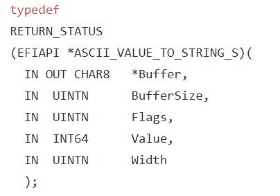
{xxxxxxxx-xxxx-xxxx-xxxx-xxxxxxxxxxxx}where ‘x’ stands for a hexadecimal digit. - An interface, which can take the form of any binary structure. Even though the UEFI specification doesn’t place any restrictions on the format of the interface, most protocols are designed to make the interface take the form of a vtable, i.e. an array of function pointers. By doing so, every client that gets a pointer to the interface (we’ll see shortly how it’s done in practice) can use it to invoke the functions associated with it.To complete the previous example, the interface for the Print2 protocol is defined like this:where each of the structure’s members is actually a function pointer. For example, the last member (AsciiValueToStringS) is prototyped as follows:
- A unique identifier, in the form of a GUID (a 128-bit integer, whose generation process guarantees uniqueness with a negligible probability of collisions). Notation wise, GUIDs are typically written as

To make a UEFI protocol available to other modules, we can use one of the following services: InstallProtocolInterface(), ReinstallProtocolInterface() or InstallMultipleProtocolInterfaces(). In addition to the GUID identifying the protocol and the pointer to the interface, all these services expect an additional argument of type EFI_HANDLE. This argument is an opaque value representing the caller module (in most cases – its base address). By taking the value of this EFI_HANDLE argument into account, we can differentiate between multiple implementations of the same interface, each offered by a different module.
To consume a UEFI interface, one can either use the LocateProtocol() or OpenProtocol() services. The main difference between the two is that LocateProtocol() simply returns the first protocol instance that matches the given GUID, while OpenProtocol() expects the caller to pass in an additional EFI_HANDLE argument to fully disambiguate which concrete implementation of the protocol is requested.
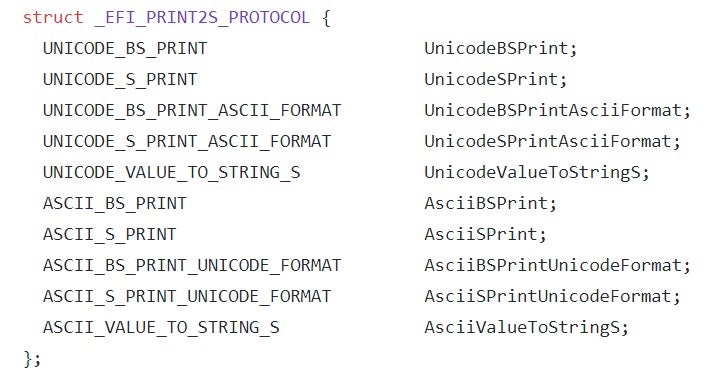
In addition, the caller can also enumerate all EFI_HANDLES implementing a given protocol by using LocateHandleBuffer(). Thus, a common practice among UEFI developers is to first invoke LocateHandleBuffer() to get an array of all module handles implementing a specific protocol, then iterate over it while calling OpenProtocol() for each entry.
Figure 2 – LocateHandleBuffer() and OpenProtocol() can be used in conjunction to process multiple implementations of the same interface (source: edk2-docs)
Runtime Services
Unlike the boot services which are only callable for the duration of the boot process, runtime services are kept in memory even after a UEFI-compliant bootloader passes control to the operating system’s kernel. Despite their availability, the OS is not obligated to take advantage of them in any meaningful way. Windows’ philosophy, for example, is to limit access to UEFI services during runtime, and instead give preference to OS native drivers followed by ACPI runtime support.
Compared to the plethora of available boot services, the list of supported runtime services is relatively short. The only subset of services which are of special interest to us are those that deal with UEFI NVRAM variables. These services, namely GetVariable(), SetVariable() and QueryVariableInfo(), will be discussed in future posts, when we’ll talk about UEFI fuzzing.
4. Manual Reversing of UEFI Images
As mentioned above, UEFI modules come in one of two possible executable file formats:
-
Portable Executable (PE): The PE file format is mostly well-known for its ubiquitous use by the Windows operating system, where standard user applications (.EXE), shared libraries (.DLL), control panel applets (.CPL), device drivers (.SYS) and even the kernel itself (NTOSKRNL) all share the same underlying file format. As such, the PE specification should already be familiar to anyone who’s done some low-level research and development on the Windows platform, so we’ll not go into the full details here. If you wish to deepen or refresh your knowledge regarding various PE concepts and structures, check out this excellent article on the OSDev.org Wiki page.In the context of UEFI, PE files comprise most of the executables found on a typical firmware image. They can encapsulate both 32- and 64-bit code, and execute “late” in the boot sequence, usually starting with the DXE phase. Although the PE files used by UEFI are identical in format to those used by Windows, some of the format’s features are not typically used (for example, UEFI modules don’t import other modules using IMAGE_IMPORT_DESCRIPTORs). Also, the signature for the entry point is quite different from that of Windows. It is usually prototyped as:
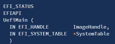 Figure 3 – The UEFI entry point (source: edk2-docs)
Where EFI_SYSTEM_TABLE is a structure containing pointers to both the boot services table as well as the runtime services table.
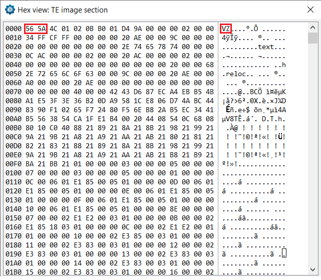
- Terse Executable (TE): The TE file format is a stripped-down version of the PE format. It was created with the aim of reducing the overhead imposed by various PE/COFF headers in PE32/PE32+ images, thus saving invaluable space on the SPI flash chip. For example, while the general PE format defines 16 different data directories, pointing to important structures such as the import table, export table or the resources section, the TE format is much more minimalistic and only defines two valid data directories: one for base relocations and one for debug information. Unlike PE files, which can host either 32- or 64-bit code, TE files are limited to 32-bit code only. As such, their usage in UEFI is limited almost exclusively to the PEI phase. Figure 4 – TE files can be easily recognized by the ‘VZ’ magic signature, as opposed to ‘MZ’ used by PE
Knowing that the UEFI consortium chose to adopt an executable format which is already in widespread use, it should come as no surprise that all major RE platforms (IDA Pro, Ghidra and Binary Ninja, among others) support parsing, loading and disassembling of UEFI modules out of the box. Still, just loading a UEFI module into IDA Pro and then staring at the assembly code is not very productive for two main reasons:
- UEFI services are never invoked directly. Instead, they are invoked indirectly through a pointer to the boot services table or runtime services table. Because of that, browsing the assembly listing for the call site yields nothing more than an obscure mnemonic in the form of call qword ptr [rax+0x140]. Given this instruction, it’s practically impossible to figure out which specific UEFI service was invoked (unless you memorized by heart the hexadecimal offsets for the various services. In that case, be our guest).
- UEFI makes heavy use of GUIDs in order to uniquely identify different entities involved in the boot process. Among these, we can find for example protocols installed via InstallMultipleProtocolInterfaces(), partitions in the GPT or even HOBs used to exchange information between different boot phases. Some projects, such as UEFTool that was previously introduced in part 1, already compiled a fair amount of these GUID definitions into a GUIDs database which can be easily imported and processed. Ideally, we’ll want to take advantage of such databases during our RE sessions.
To summarize, what we’d wish for is some sort of an automated tool to help us transform vague and ambiguous listing such as the following:
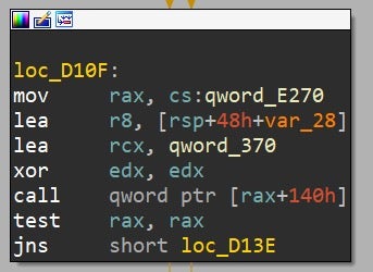 Figure 5 – typical assembly listing for UEFI code before annotation
Into a much more readable and clearer representation such as this:
Figure 6 – same assembly code after it was annotated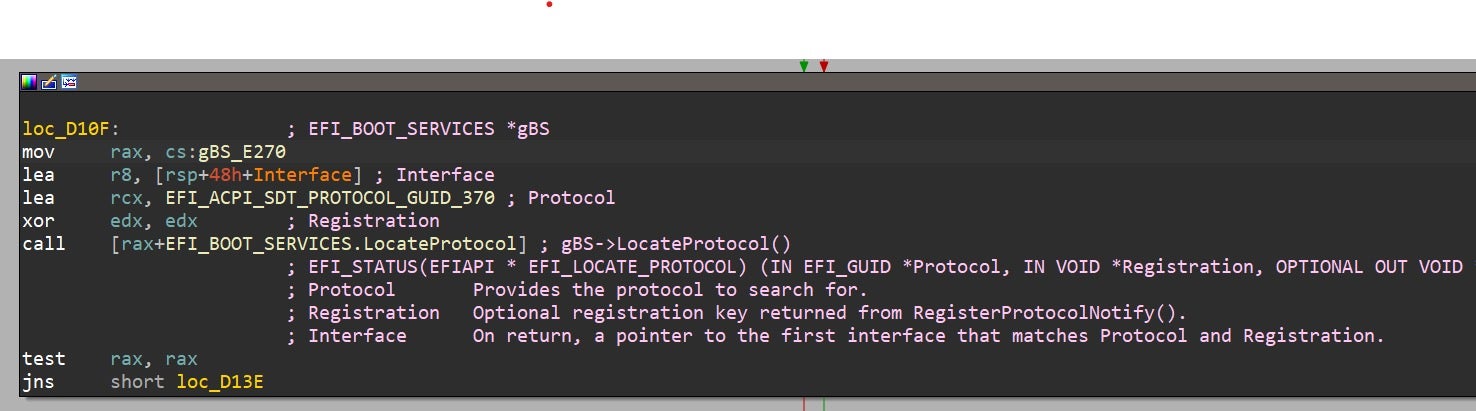
Luckily for us, throughout the years the security research community has managed to produce some high-quality tools and plugins to popular RE platforms that help make UEFI reversing much less painful. Here we’ll take a glimpse at some of the more praiseworthy ones:
- ida_efiutils: probably the oldest plugin in the list, with initial commits dating back to 2012 (!). While unmaintained, it’s still capable of resolving a fair amount of the GUIDs encountered “in the wild” as well as correctly identifying calls to boot and runtime services.
- efi_swiss_knife: one of the many UEFI-related tools created by @osxreverser. It is written in C as opposed to Python, and was mainly tested on Mac OSX environments. For more details, please refer to the accompanying blog post.
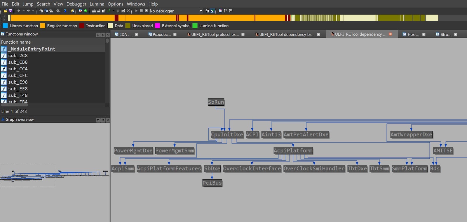
- UEFI_REtools: aims to ease the task of UEFI reverse engineering from IDA Pro. Its most unique and interesting feature is the ability to pair calls to “provider” services such as InstallProtocolInterfaces() with calls to “consumer” services such as LocateProtocol(). By doing so, it can construct a relationship graph between different UEFI modules belonging to the same firmware image:
- efiXplorer: The newest addition to the family, created by some well-known figures in the firmware security field. This plugin has a very strong emphasis on performance, plus it has the advantage of being highly maintained. Alex Matrosov recently gave a great presentation on this plugin, which also includes references to some of the other plugins mentioned above.
Tip: While reversing some UEFI modules in IDA Pro, we noticed that in some cases the Hex-Rays decompiler output was partial to the assembly listing. In these cases, chances are the decompiler was overly aggressive and eliminated some of the memory references altogether.
Figure 8 – partial decompiler output from UefiPxeBcDxe. The left branch is assumed to be always taken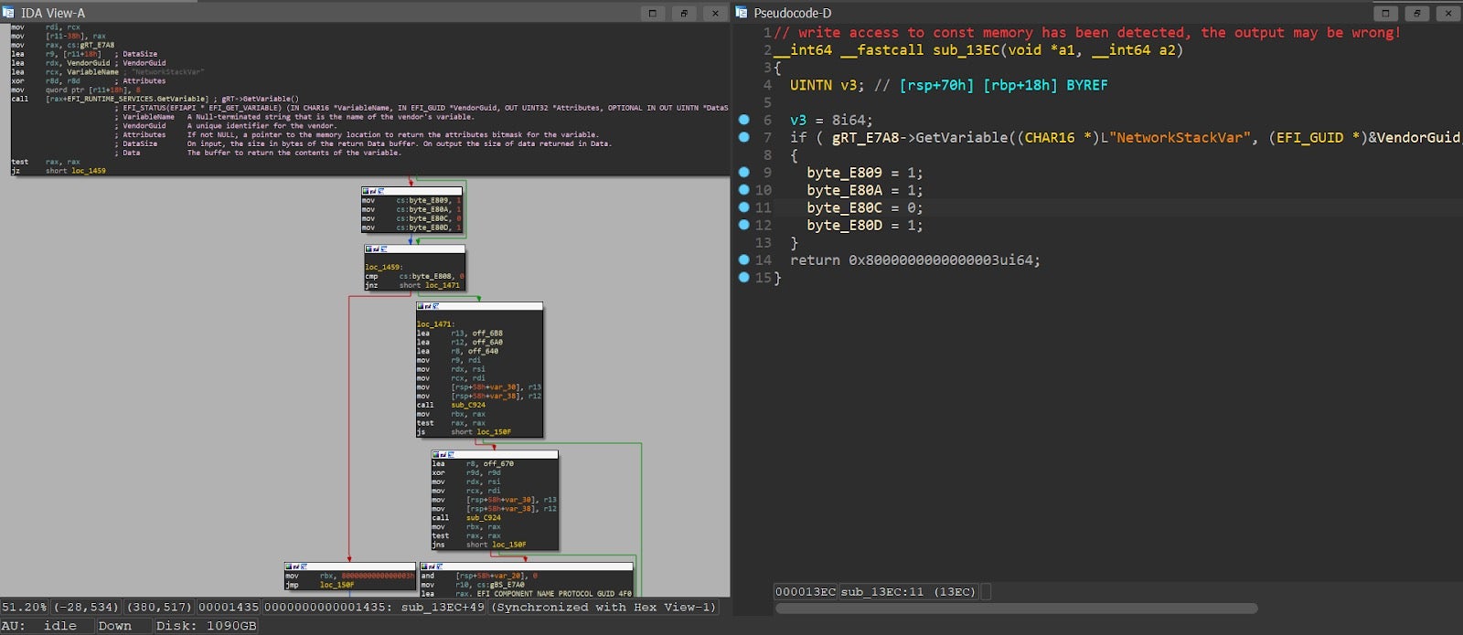
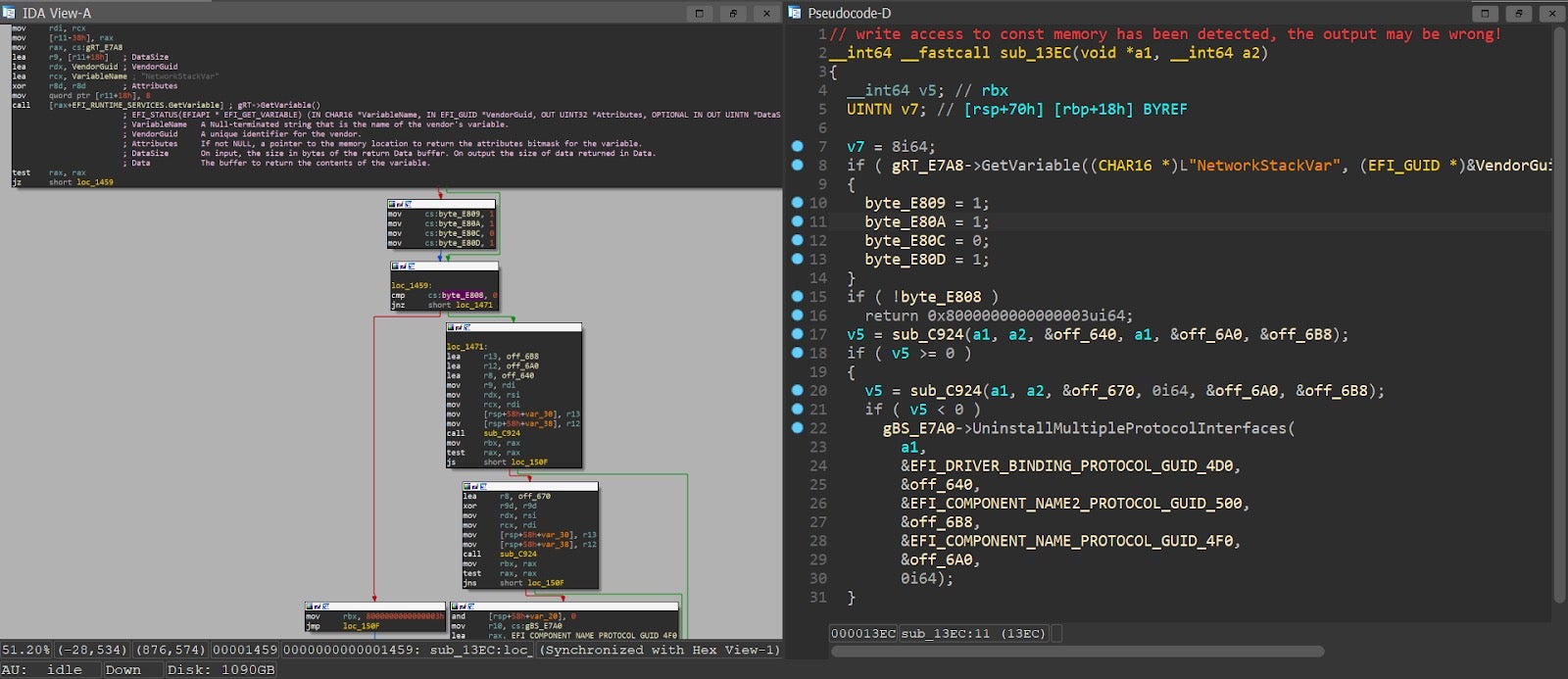
Although this can theoretically happen with every type of module, it seems to be more prevalent among UEFI images, probably because of attempts to access fixed addresses during MMIO. To work around this problem, we can either:
-
Annotate the variable which was “optimized-out” with the ‘volatile’ keyword, then decompile again.
or: - mark the entire code section as ‘writeable’, then decompile again (thanks @mztropics).
5. Debugging and Emulating UEFI Code
So far we managed to perform some basic static analysis over UEFI binaries. While definitely a big step forward, in many cases static analysis on its own is simply not enough, and it needs to be complemented by dynamic analysis techniques. In such cases, UEFI seems to impose more technical challenges than most other technologies. The main reason for that is that UEFI modules typically execute early in the boot process, long before an OS kernel is loaded into memory. As a result, it will be naive to open a UEFI module in a standard debugger and expect things to go smoothly.
One of the first major attempts to tackle this problem in a systematic approach is a project called efi_dxe_emulator, based on the renowned Unicorn emulation engine which is a fork of QEMU. However, unlike QEMU which strives to be a full system emulator, Unicorn engine focuses exclusively on CPU emulation, without having to worry too much about the nitty-gritty details of virtualizing different hardware peripherals.
Moreover, while QEMU is merely a tool, Unicorn engine is a true framework, and as such it exposes a rich set of APIs which can be consumed by a large number of programming languages via dedicated bindings. Among other things, these APIs allow the user to inspect, instrument and tinker with the execution flow, providing almost unparalleled control over the emulated code. The interested reader can find more information about the similarities and differences between Unicorn and QEMU here.
Unfortunately, Unicorn engine by itself is not enough to conduct dynamic analysis of UEFI modules. Since Unicorn’s only focus is CPU emulation, it has no a-priori knowledge of UEFI-related concepts such as boot services, runtime services, protocols or even the PE format. To accommodate these shortcomings, efi_dxe_emulator implements some of the most heavily-used UEFI services on its own. It then constructs some necessary data structures such as the boot services table and runtime services table, and places hooks to intercept all calls to these services. Once a UEFI service call has been intercepted this way, the execution flow is steered to a trampoline which jumps to a handler routine simulating the effects of the call. A more elaborate explanation of how that’s done in practice can be found here.
In addition to the core UEFI services, the emulator also implements a PE loader (so as to load UEFI images into memory), a simple heap, a handle database and a basic interactive debugger which lets you step through the emulated code. Schematically, the architecture of efi_dxe_emulator can be depicted as:
Figure 10 – the different components efi_dxe_emulator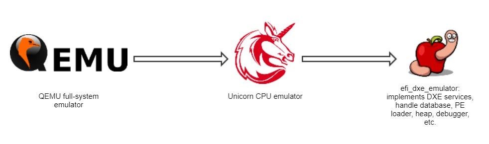
For a while, we’ve used efi_dxe_emulator as our platform of choice for conducting any UEFI-related research. In fact, we were so excited about this tool and the endless possibilities it opened for us so that we eventually ported it to Windows, and we’ve even added a couple of auxiliary features to it such as code coverage collection and integration with IDA Pro. However, the fact that efi_dxe_emulator is written in plain C, the lack of community support and the absence of any high-level interfaces eventually convinced us to look for alternatives.
Figure 11 – the Windows port of efi_dxe_emulator in action
Still, the time we spent working with efi_dxe_emulator was not in vain. Given the vast experience we’ve gained from this tool, we had a much better chance of correctly characterizing our requirements from the new emulation framework we seek:
- Being actively developed and maintained by the security research community
- Written in a friendly, high-level language such as Python. At the very least, the framework should provide appropriate bindings to such language
- Provide higher-level primitives than Unicorn engine itself. Ideally, we shouldn’t concern ourselves with loading executable images, managing the heap or implementing debugger commands.
- Integration with a fuzzing engine such as AFL is a significant advantage.
Luckily for us, it didn’t take us too long before we bumped into a new emulation framework, called Qiling. Based on the list of criteria we’ve just outlined, this new framework seemed to fit our needs almost perfectly:
- It is being actively developed by the community, with new pull-requests being proposed on a nearly daily basis. In addition, the framework was recently featured on a number of major conferences such as ZeroNights, NULLCON and HITB and created a lot of positive buzz.
- Written entirely in Python, thus enabling a very quick development and testing cycles.
- Although based on the Unicorn engine for performing core CPU emulation, Qiling goes a lot farther and offers some very useful layers on top of it. These include loaders for various executable file formats, a heap implementation and even a GDB stub to enable debugging of the emulated code. A detailed comparison between Qiling and Unicorn can be found here.
- Qiling is able to leverage AFL++, a community-driven fork of AFL, to perform coverage-guided fuzzing over the emulated code.
Schematically, the architecture of Qiling and its relationships with the other technologies mentioned can be depicted as:
Figure 12 – the roadmap to the UEFI fuzzer
6. Adding UEFI Support to Qiling
Like we discussed in section 3 (Core UEFI services) UEFI DXE modules run in an environment similar to a rudimentary OS. They have APIs they can call and methods they can use to communicate with other modules. For that reason we decided to implement the UEFI support in Qiling as an OS module.
To achieve good DXE module execution support in Qiling we had to achieve the following goals:
- Create an UEFI “OS” module.
- Create a loader for UEFI PE files.
- Implement the boot and runtime services in Python so they can be easily overwritten by Qiling users.
- Implement a few protocols that are used by many DXE modules and are usually implemented by PEI modules or DXECore (the dispatcher in DXE phase).
Most of the UEFI implementation is located in the os/uefi directory, however because the loader has a big role in loading, relocating and executing the modules it is also an important part. The run function in os/uefi/uefi.py is the main function of UEFI execution, however it is executed after the run function of loader/pe_uefi.py did the heavy lifting of loading the modules and installing the hooks and protocols.
While at least one module is loaded by the pe_uefi.py run function we’ve included support for dynamic loading of modules, which allows the loading of dependencies when they are detected by calling ql.loader.map_and_load.
The bootup.py and runtime.py modules are in charge of both installing the hooks for the bootup and runtime services and include the hooks implementation.
shutdown.py includes hooks for end of execution of a module and are used to load the next module or get back to the previous module in case of preemptive execution while a module is already running (In case of loading a module from a hook with the execute_now=True argument).
The loader starts by mapping space for the stack and heap. It allocates a buffer on the heap for the EFI_SYSTEM_TABLE (the main struct that every DXE module gets as and argument when it’s executed) The EFI_SYSTEM_TABLE include pointers for the RuntimeServices and the BootServices structures, we write all the structs to the same heap buffer after the EFI_SYSTEM_TABLE. We fill the tables using ctypes classes that we generated from UefiSpec.h and other header files included in the EDK II project. We then serialize the objects to the emulated heap.
For the function hooks we reserve space on the heap for each function (pointer size – 8 bytes, for alignment) and set a hook on that address. Qiling already had a great hooking mechanism. We only had to create a UEFI hook function decorator to use the correct calling convention. Other than the services tables we’ve already talked about, the loader also installs a configuration table that contains a HOB_LIST and a EFI_DXE_SERVICES table.
EFI_DXE_SERVICES is an interface that allows modules to manage memory and I/O spaces including defining new ones, removing them, setting their capabilities and retrieving a map of them. To save development time we decided not to implement the functionality of this interface, so we only implemented stub functions that return error code values. In case when the functionality of any of the functions needs to be implemented it can be done by overwriting the hook using the set_api function or by extending Qiling.
For reasons that will be explained in the future, many modules crash or don’t fully run when we try to execute them since they assume a few protocols are already installed. In an attempt to support as many modules as we reasonably can, we’ve implemented a few protocols as part of Qiling. Other protocols will have to be implemented on a per-project basis or maybe pushed to Qiling if they are general enough and allow many modules to run.
The protocols we’ve implemented are: EFI_SMM_BASE2_PROTOCOL, EFI_MM_ACCESS_PROTOCOL and EFI_SMM_SW_DISPATCH2_PROTOCOL. As can be deduced from their name, they are all related to SMM (System Management Mode) and implementing them allows many SMM modules to be executed.
Much like EFI_DXE_SERVICES for implementing the SMM protocols we also chose to limit development time and implement just the interfaces and not all the functions that they support. We always return false from the InSmm function indicating that the system is currently not running in SMM and most other functions return error codes. We use the same hooks for both SMM and non-SMM mode BootServices functions. Since we are not in SMM mode the SMM_SW_DISPATCH2_Register function executes the callback immediately.
Other than these protocols, we also install a per module EFI_LOADED_IMAGE_PROTOCOL that is installed every time a module is loaded and registered with the module’s handle.
Using Qiling for UEFI Emulation:
The simplest way to use Qiling to emulate UEFI is using the Qiling qltool.
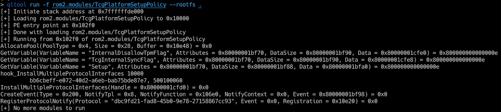
In this example we can see that the GetVariable function returns an error because we didn’t initialize the variable store. We can provide the variables as a dictionary in a pickel file. Later we will release a script to generate the pickel from a UEFI ROM image.
Figure 14 – Executing a UEFI module with variables values loaded from a file.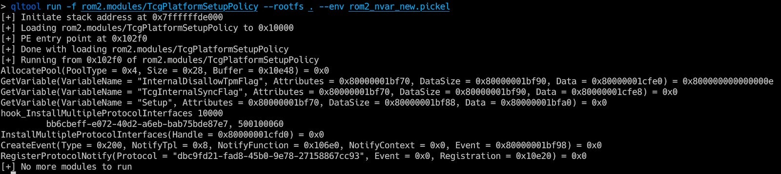
A more complex example is provided at examples/simple_efi_x8664.py (part of the Qiling repo):
import sys import picklesys.path.append("…")
from qiling import *
from qiling.const import *
from qiling.os.uefi.const import *def force_notify_RegisterProtocolNotify(ql, address, params):
event_id = params[‘Event’]
if event_id in ql.loader.events:
ql.loader.events[event_id][‘Guid’] = params[“Protocol”]
# let’s force notify
event = ql.loader.events[event_id]
event[“Set”] = True
ql.loader.notify_list.append((event_id, event[‘NotifyFunction’], event[‘NotifyContext’]))return EFI_SUCCESS return EFI_INVALID_PARAMETERdef my_onenter(ql, param_num, params, f, arg, kwargs):
print("\n")
print("=" * 40)
print(" Enter into my_onenter mode")
print("=" * 40)
print("\n")
return param_num, params, f, arg, kwargsif name == “main”:
with open(“rootfs/x8664_efi/rom2_nvar.pickel”, ‘rb’) as f:
env = pickle.load(f)
ql = Qiling([“rootfs/x8664_efi/bin/TcgPlatformSetupPolicy”], “rootfs/x8664_efi”, env=env)
ql.set_api(“hook_RegisterProtocolNotify”, force_notify_RegisterProtocolNotify)
ql.set_api(“hook_CopyMem”, my_onenter, QL_INTERCEPT.ENTER)
ql.run()
In this example we can see that loading a module and executing it only takes a few lines of code and even overwriting hooks is trivial using the set_api function. We can replace a hook all together or have a hook before or after the original hook code (onenter / onexit). In this example we know that the module will call RegisterProtocolNotify to register a callback when a protocol becomes available, here we set the event to the triggered state even that the protocol is not available (We didn’t load the module that implements it) and add the callback function pointer to the notify_list, so it will be called when the modules finishes the execution of its main function. We execute one callback from the notify_list every time a module returns from execution and only when we are done with the callbacks, we execute the next module on the modules list.
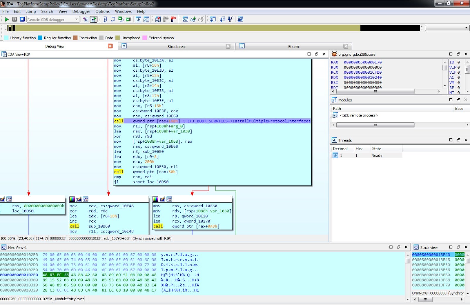
Debugging using Qiling is very easy as well and can be achieved using qltool or a dedicated script. Since a gdb server is included in Qiling, any client can be used including gdb and IDA Pro. When using qltool the –gdb 127.0.0.1:9999 needs to be added when debugging locally or –gdb 0.0.0.0:9999 when debugging from a remote computer.
Figure 15 – Debugging a UEFI module using GDB in terminal. Figure 16 – Debugging a UEFI module using IDA Pro.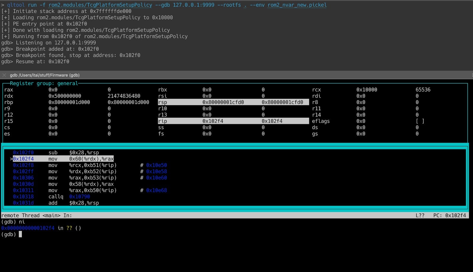
7. What Comes Next?
We came a long way in this post. We went from nothing more than manual analysis of UEFI modules to building a full-featured UEFI emulation environment capable of tracing and debugging UEFI code. The obvious question that is usually raised in these scenarios is “what comes next?”. We’ll take advantage of the remainder of this section to hint at several possible vectors for making progress.
First of all, it’s important to realize that so far we’re only capable of properly emulating individual UEFI modules. In reality, UEFI modules highly depend on each other and usually work in tandem to achieve certain goals. To some degree, emulating a single UEFI module is equivalent to loading a binary without mapping all the shared libraries it depends on to function properly. As such, emulation of individual modules has some serious limitations.
To remedy this, we should add to the UEFI loader some sort of an orchestration layer. Ideally, this layer would automatically resolve dependencies between modules and guarantee that a module will only be loaded after all its dependencies have been resolved. Using such an orchestration layer will allow us to gradually move from emulation of individual modules into emulation of entire FVs (for example the volume that hosts the DXE phase).
Figure 17 – When emulating TcgDxe in isolation, it fails to locate a necessary protocol and bails out. 0x800000000000000e is the status code for EFI_NOT_FOUND.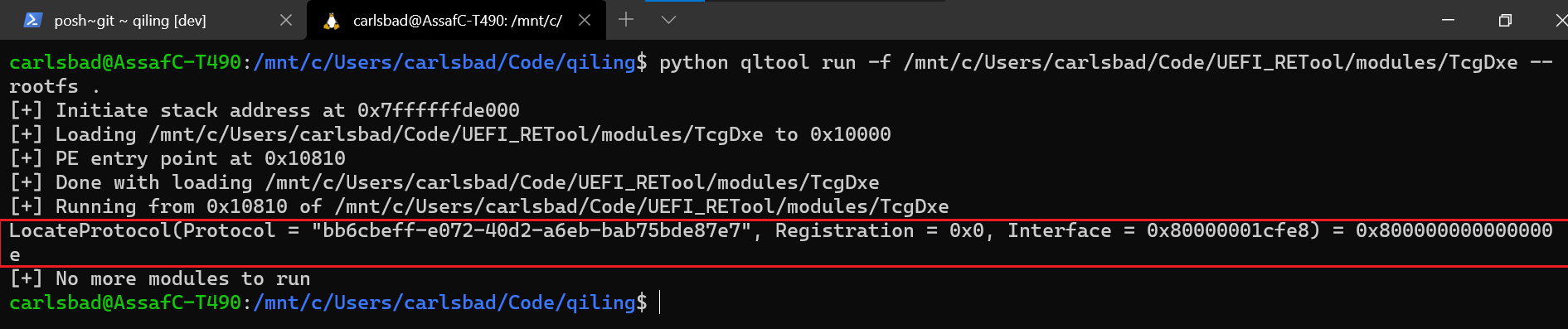
Secondly, when reviewing the features offered by Qiling, we briefly mentioned that it has a solid interface to AFL++, a fork of the vanilla AFL that can (among other things) fuzz any piece of code emulated by Unicorn engine. It should come as no surprise that we were very tempted to combine these two worlds and develop a fuzzer on top of Qiling and AFL++ that can actually be used to fuzz UEFI code. Both topics will be discussed in detail during the next parts, so stay tuned.
The post Moving From Manual Reverse Engineering of UEFI Modules To Dynamic Emulation of UEFI Firmware appeared first on SentinelLabs.
Article Link: https://labs.sentinelone.com/moving-from-manual-re-of-uefi-modules-to-dynamic-emulation-of-uefi-firmware/