Hi everyone, this is the part 2 of Assembly Language programming and shellcoding series. If you have not read my previous post, you can read it here. In previous blog, I tried to explain why I chose assembly language programming instead of going for another certification and other blabbering. In this blog, we will look into processor architecture (Intel specifically) and we will try to understand how processor works. Let me confess, this blogpost is full of theory, really dry and boring. I’ll try my best to keep this post interesting.
What is CPU?
When I was taking computer basics lessons, my teacher told me that “CPU is heart of computer”. Now after so many years, I can say, CPU is more like brain of computer. Reason? Like brain, CPU does most of computational work. Other components which does similar kind of job is Graphics unit. Now question arises, how these things works? At most basic level, it’s a grid (or labyrinth?) of logic gates. If you sliced a typical Intel processor horizontally and super-zoomed it under some very powerful microscope, you can see something like this:
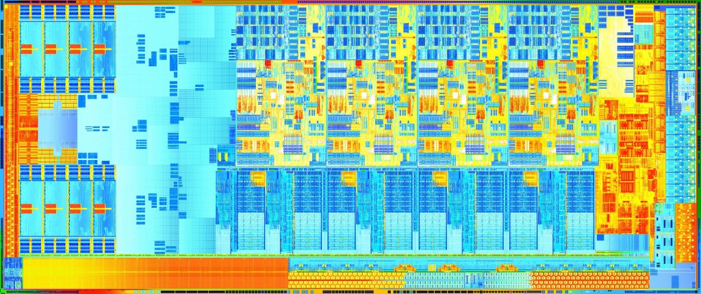
Amazing, isn’t it? But honestly, this diagram is not going make any sense in terms of understanding its functionality. To understand this architecture (rather any architecture), we need to simplify such complex diagram into simple block diagram. Little bit of googling give simplified architecture diagram for i-series processor family.
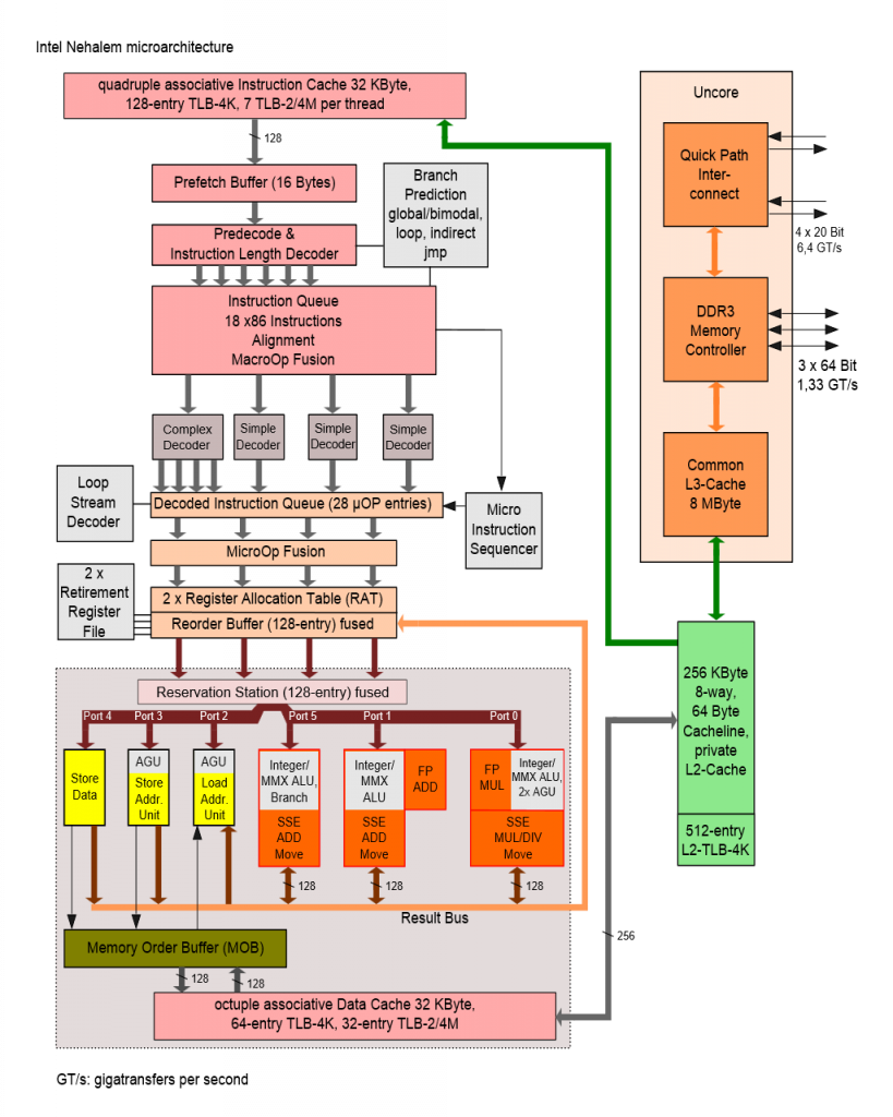
Now to learn assembly language and do shellcoding, you should know about components from this diagram. But its not necessary that you know everything about each and every component and flow. As a beginner, we need to understand high level computer organization, high level CPU organization and finally core CPU components. If you are curious enough, then find out version of Intel processor your computer is using and find corresponding manual online for free. So, let’s start with computer organization.
Computer System Organization:
If we draw simplest block diagram of computer system, it might look like this.
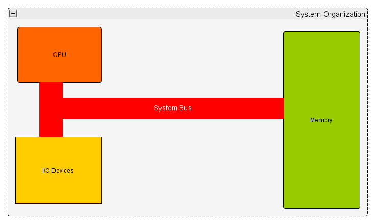
Very simply, it works as follow:
a. Program is loaded into memory.
b. CPU fetches and executes instructions, one by one. (This is called as Fetch-Execution cycle)
c. Result of executed instruction will change state of CPU, Memory as well as I/O devices.
Now CPU is again divided in following logical components:
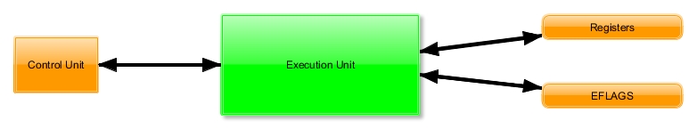
a. Control Unit: This component defines how to respond to various instructions. It deals with Retrieve/Decode instructions, Retrieve/Store data in memory.
b. Execution Unit: This component performs actual operations and calculations.
c. Registers: Used as variables in ASM program.
d. Flags: Used to define “Event” and “State” of CPU.
As we got basic idea of CPU functionality, we can look the components we will be using while programming and shellcoding.
Core components of Intel processors:
Intel Processors Architecture consist of various types of Registers, Cache, etc. Out of which following are most important for our programming purpose.
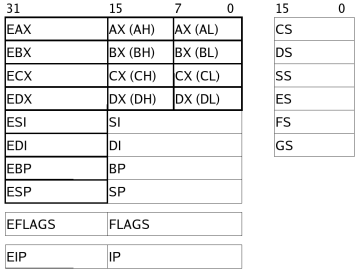
1. General Purpose Registers (GPR): Programmer can use these registers as per requirement. Even though these are GPRs, Intel has defined some convention for these registers (During actual programming we will see of those). Let’s see the description provided by Intel for every register.
a. EAX: Extended Accumulator Register. Will store operands and operation result. Also used for I/O port access and interrupt calls etc.
b. EBX: Extended Base Register. Used as base pointer to memory access.
c. ECX: Extended Counter Register. Used for loop counter and shifts.
d. EDX: Extended Data Register. Similar to EAX.
e. ESI: Extended Source Index Register. String and memory array copy operations.
f. EDI: Extended Destination Index Register. String and memory array copy operations.
g. EBP: Extended Base Pointer. Holds base address of stack section of running process.
h. ESP: Extended Stack Pointer. Holds Top of stack address.
We can see the length and allowed logical division of registers. For example, AL = 8 bits (0 to 7), AH = 8 bits (8 to 15), AX = 16 bits (0 to 15), EAX = 32 bits (0 to 31) and so on…
2. Segment Registers: Segment registers hold the segment address of various items. They are only available in 16 bits values. They can only be set by a general register or special instructions.
a. CS: Code Segment Register. Holds code segment of program you are running.
b. DS: Data Segment Register. Holds data which your program will access.
c. SS: Stack Segment Register. Holds stack segment of your program.
d. ES, FS, GS: These are extra segments.
3. EIP: Extended Instruction Pointer. This register contains the address of next instruction to be executed.
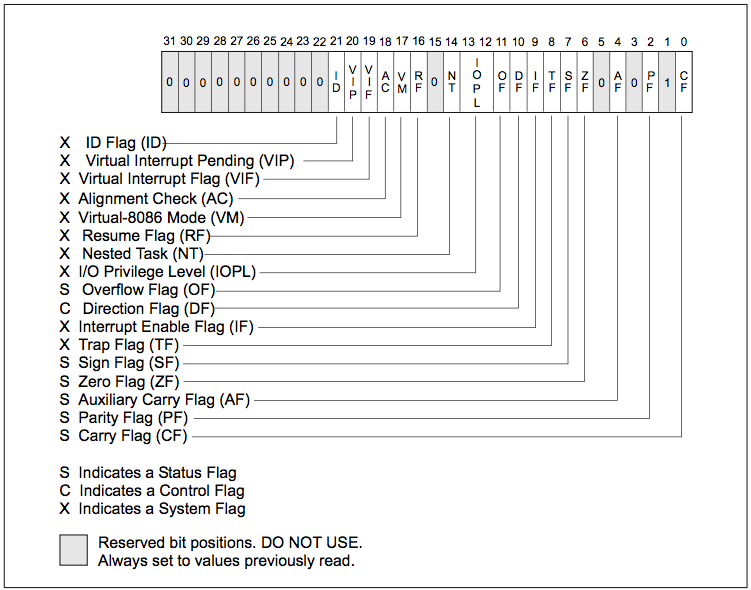
4. EFLAGS: These flags define state of processor. They either “SET”, “RESET” or “CLEAR” based on type of operation you perform. They are as follow:
I can understand that you are bored to hell by reading theory and I also skipped large amount of theory to avoid unnecessary overheads. However, we will cover every necessary detail once we start with actual programming part. But that’s still way ahead, because in next blogpost we will be looking in Linux OS architecture and organization. Till then, Auf Wiedersehen!!!!
The post Getting ready for Assembly Language Programming – Anatomy of Intel Processor appeared first on ScriptDotSh.
Article Link: https://scriptdotsh.com/index.php/2018/05/13/anatomy-of-intel-processor/